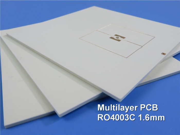
Hybrid RF and High Frequency 4-Layer Circuit Boards Built on 16mil RO4003C + FR-4 with Immersion Tin
(Printed Circuit Boards are custom-made products; the images and parameters shown are for reference only.)
Introduction
Hello Everyone,
Today, we will discuss two types of 4-layer high frequency PCBs constructed with a 16mil core of RO4003C.
The design features a 4-layer structure, which is relatively simple and cost-effective, making it ideal for entering new markets.
Stack-Up Overview
Let’s examine the stack-up first.
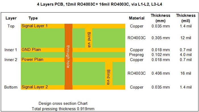
In the stack-up, the first and second layers consist of a 12mil core of RO4003C, while the third and fourth layers use a 16mil core of RO4003C. The fixed thickness of the core is crucial for maintaining the electrical length of RF lines on the circuit board. The two cores are bonded using bonding film (Prepreg).
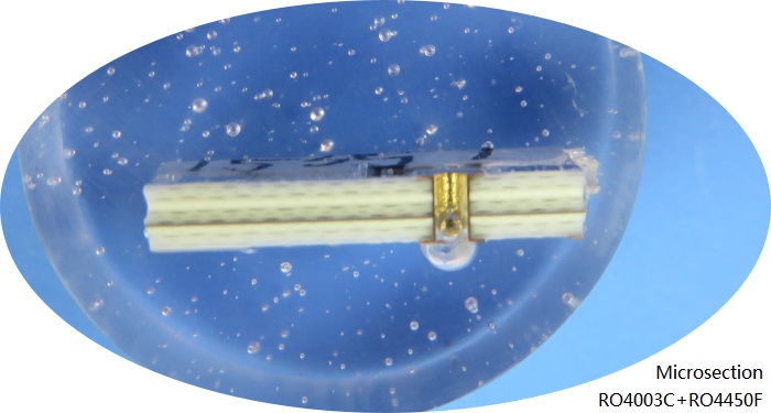
Currently, two types of prepreg are used in multilayer high frequency PCBs: FR-4 dielectric and high frequency dielectrics, such as RO4450F, Cuclad 6250, and Taconic’s FastRise-28 (FR-28).
The copper weight on the inner layer is 0.5 ounces, while the outer layers are 1 ounce. Blind vias are drilled through both cores.
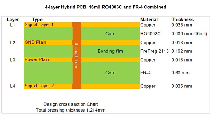
The second board is a mixed PCB, utilizing FR-4 for layers three and four, while high frequency signals transmit through the high frequency substrate in layers one and two. The thickness of the dielectric material and FR-4 can be adjusted according to specific applications.
Applications
The 16mil RO4003C hybrid PCB has diverse applications, including:modular oscilloscopes;antenna combiners;balanced amplifiers;4G antennas.
Advantages
The advantages of the 16mil RO4003C hybrid PCB include:
1.Stable Dielectric Constant: RO4003C maintains a stable dielectric constant across a broad frequency range, making it an excellent substrate for broadband applications.
2.Reduced Signal Loss: It minimizes signal loss in high frequency applications, meeting the evolving demands of communication technology.
3.Cost-Effectiveness: The cost is lower compared to stack-ups using all low-loss materials.
Standard Thickness Options
The standard thicknesses available for RO4003C are 0.008” (0.203mm), 0.012” (0.305mm), 0.016” (0.406mm), 0.020” (0.508mm), 0.032” (0.813mm), and 0.060” (1.524mm). These thicknesses are readily available in-house. We welcome your inquiries and patronage.
For more detailed specifications, please refer to the Data Sheet of Rogers 4003C (RO4003C).
Data Sheet of ROgers 4003C(RO4003C)
RO4003C Typical Value |
|||||
Property |
RO4003C |
Direction |
Units |
Condition |
Test Method |
Dielectric Constant,εProcess |
3.38±0.05 |
Z |
|
10 GHz/23℃ |
IPC-TM-650 2.5.5.5 Clamped Stripline |
Dielectric Constant,εDesign |
3.55 |
Z |
|
8 to 40 GHz |
Differential Phase Length Method |
Dissipation Factortan,δ |
0.0027 |
Z |
|
10 GHz/23℃ |
IPC-TM-650 2.5.5.5 |
Thermal Coefficient of ε |
+40 |
Z |
ppm/℃ |
-50℃to 150℃ |
IPC-TM-650 2.5.5.5 |
Volume Resistivity |
1.7 x 10¹⁰ |
|
MΩ.cm |
COND A |
IPC-TM-650 2.5.17.1 |
Surface Resistivity |
4.2 x 10⁹ |
|
MΩ |
COND A |
IPC-TM-650 2.5.17.1 |
Electrical Strength |
31.2(780) |
Z |
Kv/mm(v/mil) |
0.51mm(0.020") |
IPC-TM-650 2.5.6.2 |
Tensile Modulus |
19,650(2,850) |
X |
MPa(ksi) |
RT |
ASTM D 638 |
Tensile Strength |
139(20.2) |
X |
MPa(ksi) |
RT |
ASTM D 638 |
Flexural Strength |
276 |
|
MPa |
|
IPC-TM-650 2.4.4 |
Dimensional Stability |
<0.3 |
X,Y |
mm/m |
after etch+E2/150℃ |
IPC-TM-650 2.4.39A |
Coefficient of Thermal Expansion |
11 |
X |
ppm/℃ |
-55℃to288℃ |
IPC-TM-650 2.4.41 |
Tg |
>280 |
|
℃ TMA |
A |
IPC-TM-650 2.4.24.3 |
Td |
425 |
|
℃ TGA |
|
ASTM D 3850 |
Thermal Conductivity |
0.71 |
|
W/M/oK |
80℃ |
ASTM C518 |
Moisture Absorption |
0.06 |
|
% |
48hrs immersion 0.060" |
ASTM D 570 |
Density |
1.79 |
|
gm/cm3 |
23℃ |
ASTM D 792 |
Copper Peel Stength |
1.05 |
|
N/mm |
after solder float 1 oz. |
IPC-TM-650 2.4.8 |
Flammability |
N/A |
|
|
|
UL 94 |
Lead-free Process Compatible |
Yes |
|
|
|
|
